زبان

نقل قول کنید
نقل قول کنید
 خانه / خبر / اخبار صنایع / چگونه دستگاههای جوش لب به لب سازمان ملل چالشهای پیوسته سیم و میله را حل میکنند
 2026.07.09
 اخبار صنایع
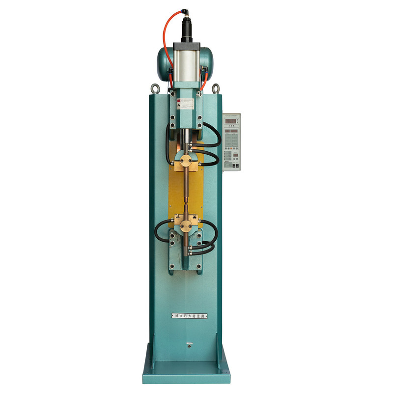
هر عملیاتی که سیم بکشد، استوک میله را تغذیه کند، یا تیغه اره نواری را اجرا کند، در نهایت با همان مانع روبرو می شود: مواد خام در طول سیم پیچ های محدودی عرضه می شود، اما این فرآیند نیاز به عرضه بدون وقفه دارد. توقف یک خط برای بارگیری مجدد زمان چرخه هزینه های مواد، ضایعات را در نقطه انتقال معرفی می کند و اپراتورها را مجبور می کند تا انتهای همپوشانی را مدیریت کنند که محصول نهایی را ضعیف می کند. به درستی مهندسی شده است دستگاه جوش لب به لب سازمان ملل متحد این گلوگاه را با ادغام دو سر سیم یا میله در یک رشته پیوسته منفرد با استحکام مفصلی که کاملاً با ماده اصلی مطابقت دارد، از بین می برد.
برخلاف اتصال همپوشانی یا چین خوردگی مکانیکی، جوش لب به لب مبتنی بر مقاومت یک پیوند متالورژیکی در سراسر سطح مقطع کامل مواد ایجاد می کند. این در مواردی که اتصال مکرراً از طریق قالبها، غلتکها یا راهنماهای اره عبور میکند، بسیار اهمیت دارد، زیرا هر درز برجسته یا نقطه ضعیف در نهایت تحت فشار چرخهای از بین میرود.
اصطلاح دستگاه جوش لب به لب سازمان ملل متحد به خانواده تجهیزات جوش لب به لب مقاومتی اشاره دارد که بر اساس یک اصل اصلی ساخته شده اند: دو سر را گیره دهید، جریان و فشار اعمال کنید و رابط را فیوز کنید. تفاوت بین مدل ها در نحوه کنترل نیروی گیره و جریان نهفته است که به نوبه خود محدوده مواد، کیفیت اتصال و سرعت تولید مناسب هر نوع را تعیین می کند.
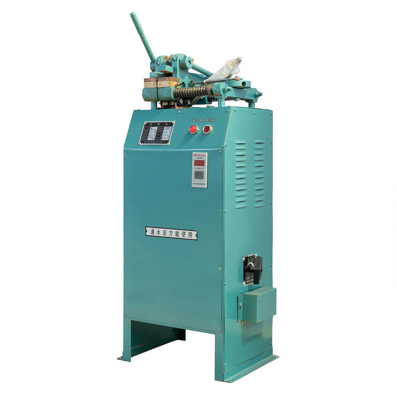
سه پیکربندی اکثر نیازهای اتصال سیم و میله را در خطوط کشش سیم، تولید فنر، تولید مش و ساخت تیغه اره نواری پوشش می دهد:
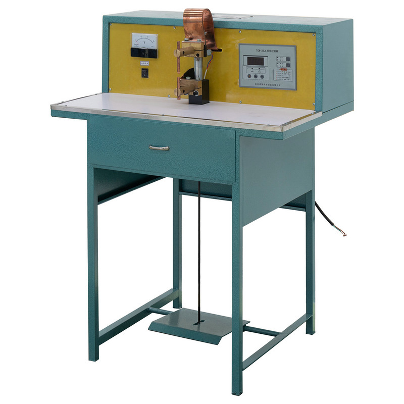
را دستگاه جوش لب به لب UN1 دستی متکی به یک مکانیسم بستن اهرمی است که مستقیماً توسط تکنسین کار می کند. از آنجایی که اپراتور هم سرعت بسته شدن و هم فشار ثابت را با احساس کنترل میکند، این پیکربندی در تنظیماتی که قطر سیم یا بخشهای میله اغلب تغییر میکند و یک چرخه خودکار ثابت نیاز به برنامهریزی مجدد دائمی دارد، به خوبی کار میکند.
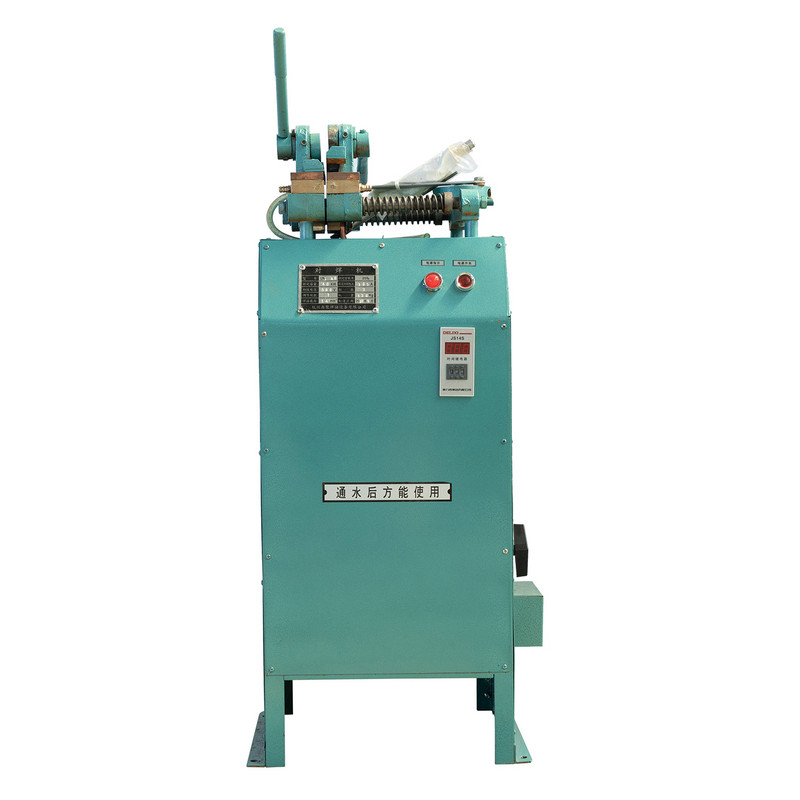
کارگاههایی که سیم کشش شکسته را در اواسط کار تعمیر میکنند، اتاقهای ابزار آمادهسازی کوپنهای آزمایشی، یا ایستگاههای توری بافی کوچک تمایل به این پیکربندی دارند زیرا زمان راهاندازی حداقل است و نیازی به هوای فشرده نیست. موازنه این است که سازگاری مفصل تا حدی به تکنیک اپراتور بستگی دارد، بنابراین آموزش و یک روش گیره مستند در اینجا بیشتر از انواع خودکار اهمیت دارد.
| صفت | رفتار معمولی |
|---|---|
| فعال سازی | گیره اهرمی دستی |
| بهترین محدوده قطر مناسب | سیم نازک تا متوسط و میله کوچک |
| تامین هوا مورد نیاز | خیر |
| ثبات چرخه | وابسته به اپراتور |
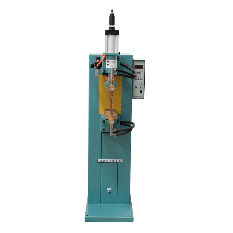
را UN2 Pneumatic Butt Welding Machine replaces the manual lever with an air cylinder, so the clamping force stays consistent from the first weld of the shift to the last. This matters in continuous production because joint quality drifts noticeably once operator fatigue affects manual clamping pressure over hours of repetitive cycles.
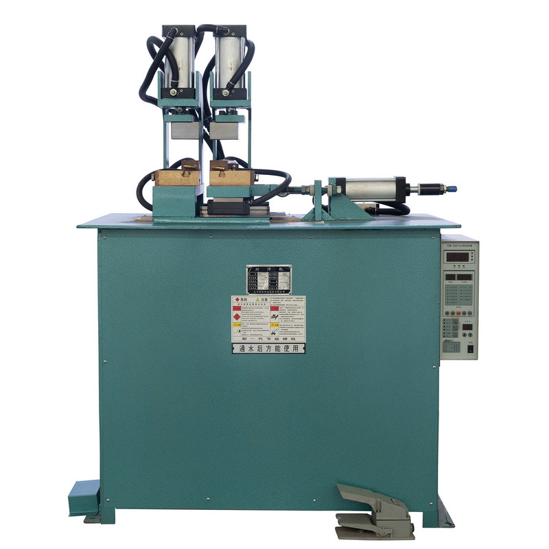
ماشین های سیم کشی خطوط تغذیه کننده، تجهیزات سردرد یا حمام های گالوانیزه مداوم معمولاً این سبک جوشکار را مستقیماً قبل از فرآیند ادغام می کنند، زیرا اتصال ضعیف یا ضعیف در پایین دست می تواند به ابزار بسیار گران تر از خود جوشکار آسیب برساند.
را دستگاه جوش لب به لب فلاش UN3 از مکانیزم فیزیکی متفاوتی نسبت به جوشکاری مقاومتی استفاده می کند. به جای اعمال فشار کامل قبل از جریان جریان، دستگاه دو سر را به صورت متناوب در حالی که جریان از قبل اعمال شده است، در تماس متناوب قرار میدهد و یک سری سریع قوسهای کوچک یا چشمک میزند که قبل از اینکه یک نیروی آهنگری نهایی اتصال را جوش دهد، رابط را تمیز و گرم میکند.
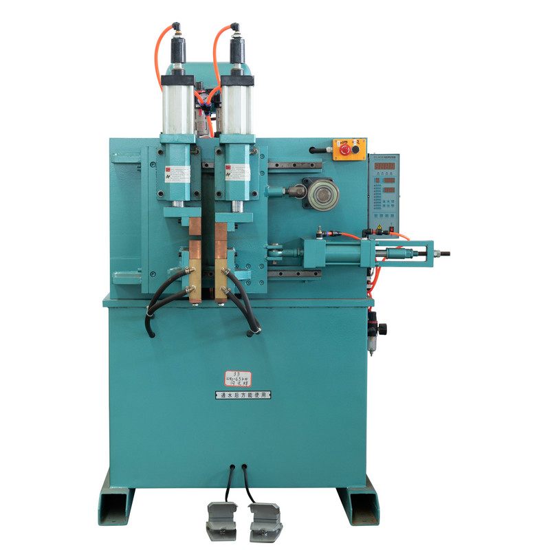
را flashing action burns off surface oxides and contamination from the mating faces before the forging stroke occurs, which is difficult to achieve with straight upset welding once the cross section grows beyond thin wire. This is why flash butt welding is the preferred process for larger rod diameters, band saw blade backs, and rolled ring stock where a clean, low-inclusion joint is critical to fatigue life.
مشاهده میدانی: سازندگان تیغه اره به طور مداوم گزارش می دهند که اتصالات جوش داده شده تحت خمش مکرر در اطراف راهنماهای چرخ نسبت به اتصالات ساخته شده با جوشکاری ناهموار با مقاومت مستقیم روی همان ضخامت مواد، بهتر مقاومت می کنند، عمدتاً به این دلیل که مرحله چشمک زن لایه های اکسید سطحی را که در غیر این صورت در داخل رابط جوش قرار می گیرند، حذف می کند.
درک دنباله کمک می کند تا توضیح دهیم که چرا کیفیت اتصال پس از تنظیم صحیح پارامترها تا این حد قابل تکرار است. این فرآیند در چهار مرحله مجزا حرکت می کند که هر کدام جنبه متفاوتی از مفصل نهایی را کنترل می کند.
هر فاز به جای اینکه بر اساس احساس قضاوت شود، زمانبندی میشود، دقیقاً به همین دلیل است که جوشکاری فلاش کنترلشده توسط ماشین، اتصالات منسجمتری را نسبت به فرآیند دستی صرفاً پس از تغییر قطر یا آلیاژ ایجاد میکند.
انتخاب سیم مناسب برای عملکرد دستگاه جوش به همان اندازه که مربوط به تنظیم دستگاه است به خود مواد مربوط می شود. قطر سیم یکسان بسته به پوشش سطح، مزاج و ترکیب آلیاژی که همگی جریان و فشار لازم برای اتصال تمیز را تغییر میدهند، میتواند رفتار متفاوتی داشته باشد. اپراتورهایی که سیم را برای خطوط خوراک جوشکار تامین می کنند باید این متغیرها را به عنوان بخشی از دستور جوشکاری در نظر بگیرند، نه فقط یک مشخصات خرید.
| وضعیت مواد | ملاحظات مشترک |
|---|---|
| سیم فولادی روشن کشیده شده است | جوشکاری با مقاومت مستقیم، حداقل تمیز کردن مورد نیاز |
| سیم گالوانیزه | برای جلوگیری از تخلخل، پوشش باید در نزدیکی محل اتصال کنده شود |
| سیم ضد زنگ | مقاومت بالاتر نیاز به تنظیم دقیق جریان دارد |
| سیم فنری سخت شده | ناحیه اتصال اغلب به بازپخت پس از جوش برای بازیابی شکل پذیری نیاز دارد |
به عنوان یک اصل کلی، سیم نازکتر به نفع جوشکاری با مقاومت در دستگاههای بادی یا دستی است، در حالی که میلهها و نوارهای ضخیمتر از عمل تمیز کردنی که جوشکاری فلاش ارائه میکند سود میبرد. تطبیق نوع دستگاه با مشخصات مواد، کار مجدد را کاهش می دهد و نرخ خرابی اتصالات را در طول دوره های تولید طولانی پایین نگه می دارد.
را practical value of these machines becomes clearer when mapped against the operations that depend on continuous strand supply:
در هر مورد، هدف اساسی یکسان است: از بین بردن زمان خرابی و ضایعات ناشی از بارگیری مجدد مواد خام، در حالی که اتصال را به اندازه کافی قوی نگه دارید که ابزارهای پایین دست هرگز آن را به عنوان نقص ثبت نکنند.
سایش الکترود و گیره شایع ترین علت کاهش تدریجی کیفیت اتصال در هر دستگاه جوش لب به لب است. با ساییدگی فک های گیره، مقاومت تماس به طور ناهموار افزایش می یابد، که حتی زمانی که تنظیم فعلی تغییر نکرده است، به صورت تشکیل ناراحتی ناسازگار ظاهر می شود. یک روال بازرسی کوتاه روزانه این موضوع را قبل از اینکه بر دوره کامل تولید تأثیر بگذارد، نشان می دهد.
مفصلی که از نظر بصری تمیز به نظر میرسد اما در تست خمش شکست میخورد، تقریباً همیشه به صورتهای جفتگیری آلوده یا نیروی گیرهای که از محدوده خارج شده است، بازمیگردد، نه یک محدودیت اساسی فرآیند.
جوشکاری مقاومتی فشار گیره کامل را قبل از جاری شدن جریان اعمال میکند و برای فیوز کردن انتهای تمیز و از پیش آماده شده به گرما به اضافه فشار متکی است. جوش لب به لب فلاش باعث ایجاد قوس متناوب قبل از ضربه آهنگری میشود که سطوح جفتگیری را به عنوان بخشی از چرخه تمیز میکند و آن را برای بخشهای بزرگتر یا مواد کمتر بکر مناسبتر میکند.
اکثر دستگاه های جوش لب به لب برای یک محدوده قطر مشخص رتبه بندی می شوند زیرا نیروی گیره، ظرفیت جریان و هندسه الکترود با آن محدوده مطابقت دارد. مواد در حال اجرا خارج از محدوده رتبه بندی شده معمولاً اتصالات ناسازگاری ایجاد می کنند حتی اگر دستگاه به طور فیزیکی مواد را بپذیرد.
هنگامی که پارامترها به درستی با مواد مطابقت داشته باشند و اتصال به درستی تراشیده شود و در صورت نیاز، تنش کاهش یابد، اتصال می تواند به عملکرد کششی سیم اطراف نزدیک شود. نتایج واقعی بر اساس آلیاژ، قطر و عملیات پس از جوش متفاوت است، بنابراین آزمایش نمونه بر روی هر دسته مواد جدید توصیه می شود.
نه لزوما. واحدهای پنوماتیک ثبات و سرعت را برای اجراهای با حجم بالا ارائه می دهند، اما واحدهای دستی برای کارهای با حجم کم، تغییر قطر مکرر یا مکان هایی بدون منبع هوای فشرده قابل اعتماد عملی هستند.
بله. پوششهایی مانند روی میتوانند در حین جوشکاری تبخیر شوند و اگر قبلاً از ناحیه جوش تمیز نشوند، تخلخل یا آخالهایی در محل اتصال ایجاد میکنند. کندن یا پوشاندن پوشش در نزدیکی ناحیه اتصال معمولاً یکپارچگی جوش را بهبود می بخشد.
محصولات پیشنهادی $ $ $

محصول
اطلاعات تماس
+86-152-5712-5882
Fax: +86-563-2269966
شماره 21 جاده گوانگپینگ ، منطقه توسعه اقتصادی گوانگد ، شهر گوانگد ، استان آنهویی
کد QR